Best practice recommendations for the handling of landfill gas produced from landfill sites (2009).
This work makes recommendations for the best practical options for the treatment and utilisation of landfill gas produced at landfill-waste treatment facilities in Leeds. The production of landfill gas is evaluated over the lifetime of the landfill site and design recommendations are provided in order to sustainably recover, treat and utilise the landfill gas as an energy source.
ACRONYMS
DoE DEPARTMENT OF ENVIRONMENT
EA ENVIRONMENTAL AGENCY
EPA ENVIRONMENT PROTECTION AGENCY
HDPE HIGH DENSITY POLYETHYLENE
LFG LANDFILL GAS
USEPA UNITED STATES ENVIRONMENTAL PROTECTION AGENCY
LIST OF FIGURES
FIG 1 Typical vertical well design
FIG 2 A typical flare stack design
FIG 3 Graph showing methane production
FIG 4 Graph showing estimated annual power generation
FIG 5 Graph showing power generation
FIG 6 Overall gas handling system arrangement
1 INTRODUCTION
The regulatory guidelines for landfill planning permission obliges landfill operators to propose methods for the handling of the landfill gas (LFG) to be generated from the site, and the site restoration activities to be put in place on the completion of the landfill (MoTE, 1998).
Over the productive lifetime of a landfill site, which can range between 20 and 80 years, depending upon rate of waste degradation, the site will continue to gas (produce LFG) heavily. It is imperative that such gas is handled properly as it can be of economic value or economic and environmental de-value, depending on the handling system embraced for the landfill gas.
‘The UK landfill gas resource is estimated to be equivalent to around 6.75 TWh/year (around 2 % of the current UK electricity demand)’ (Tetchner, 2008). ‘Landfill gas consists of a mixture of flammable, asphyxiating and noxious gases and may be a hazard to health. When air is permitted to mix with landfill gas, flammable mixtures may be produced which if contained, can give rise to explosion’ (DoE, 1988).
Landfill designers/engineers also need consider the intended use of the landfill facility after operations. Whatever use is decided upon needs to well-matched with the material components and physical arrangement of the capping system, the surrounding landscape and current land-use practices as specified in the applicable development plan.
This report is a follow-up of a previous report on the proposed landform project for the city of Leeds by a group of four individuals. Certain information used here shall be obtained from the previous report; therefore this report will make references to the former.
1.1 AIMS
The aims of this report include but are not limited to the following:
- To provide an outline of the gas collection and management system for the proposed landfill site.
- To provide an estimate of the LFG production using the USEPA’s landgem spreadsheet or a similar piece of software.
- To provide the anticipated power generation from the site and show how it will change over the life of the site.
- To provide plans for the eventual site restoration.
- To provide a site plan showing the main gas withdrawal points.
- To provide an indication of how the phased recovery of gas from the site over its life time will be managed.
- To show the design of a typical gas recovery well.
- To provide graphs and/or tables showing the expected gas yield and power generation from the site over its lifetime.
2 GAS-HANDLING SYSTEM
2.1 Gas Collection
The gaseous nature of LFG makes it move towards the surface and periphery of the cell layers within which it is temporarily held after release. Such movements continue to take place until the gases find a pathway out of the landfill and into the surrounding environment through diffusion. In order to effectively channel the gases out of the landfill and prevent direct release into the environment, active gas collection systems have to be put in place that will control migration and emissions, maximise gas collection for energy recovery and comply with regulations.
The proposed system for this site will entail vertical gas extraction wells with well heads spaced appropriately for proper gas collection. The greatest density of required wells will be situated at the periphery of the landform to prevent migration of gases laterally from the site (McDougall et al, 2001). The annulus of the extraction well will be backfilled with gravel and will be capped by a layer of impermeable material such as bentonite-enhanced clay.
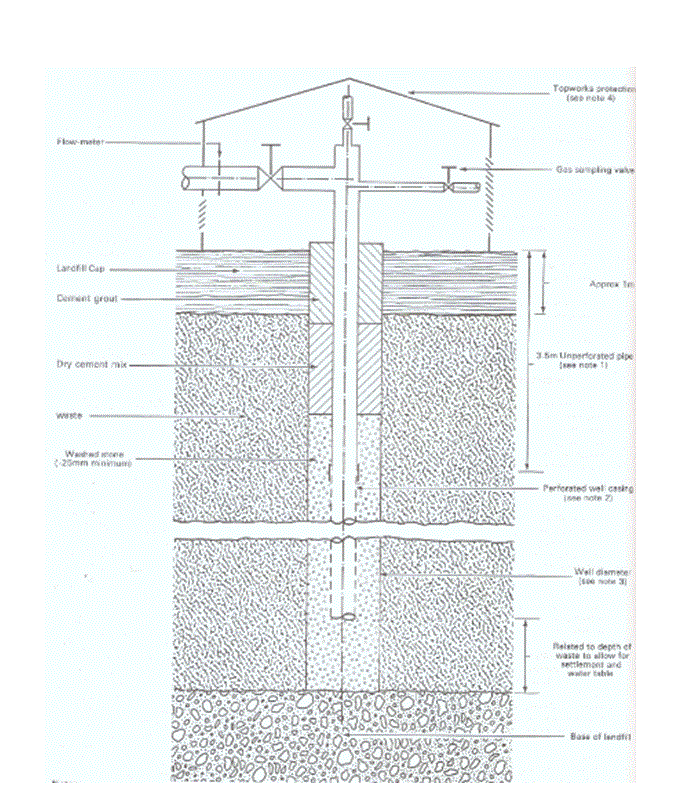
Fig.1 Typical vertical well design.
These wells will be connected by a series of plastic pipes which will direct the gas flow out of the landform. The gas-handling system will also include an enclosed flare stack, gas treatment system and power generation units.
It is important to note that under pressure, LFG is soluble and can dissolve in the leachate to be transported out of the landform. A properly designed liner system therefore acts as a barrier to prevent the escape of LFG through this medium. The liner system will be integrated with the gas collection system. Figure 1 above shows a typical design for a vertical landfill gas well.
Design Considerations:
- The vertical gas extraction wells will be spaced at two wells per hectare (this does not include the wells to be sunk at the landform periphery, which will be more densely populated; the distance between these wells will be kept at approximately 20 m). This will keep the distance between well centres at approximately 50 m.
- Each well shall have a diameter of 0.5 m and will be drilled to 80% of the waste height.
- The wells shall be cased during drilling to minimise gas escape.
- The well pipes will have a diameter of .1 m and be perforated, except for the top 3.5 m, to prevent air getting into the landfill due to suction.
- The pipes to be used for gas collection will be HDPE pipes which are not susceptible to corrosion or light and will be 120 mm diameter.
- The pipes will be laid in such a manner to allow the drainage of condensate back into the well, preventing pipe blockage.
- A centrifugal pump will be used to create the required suction for gas extraction.
- Flow-rate measurement fittings are to be installed on the wells to monitor gas flow.
2.2 Gas Treatment
In order to prepare the landfill gas for combustion, it is necessary to install pre-treatment processes before the combustion phase of the gas to prevent engine and flare stack corrosion by raw gas.
The proposed gas treatment for this site will include water and condensate knockout processes and particulate filtration.
The water and condensate knockout phase will include liquid removal with the aid of drains and a condensate knockout pot; foam removal by the use of stainless steel woven meshes before and after the knockout pot; and cyclones. This phase also includes vapour removal, which involves pre-heating, compression and then cooling the gas.
The particulate filtration phase of treatment will be achieved by the same process which also acts as a means of foam removal.
2.3 Gas Utilisation
After treatment, the gas will be channelled to the gas engines for combustion and power generation. It is proposed that lean burn gas engines manufactured by Deutz be used.
Gases in excess of the engine combustion capacity will be channelled to an enclosed flare stack for conversion to CO2 to reduce greenhouse effects. Figure 2 below shows a typical flare stack design.
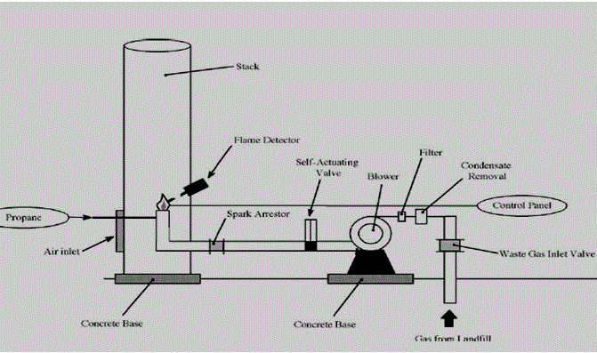
Fig.2 A typical flare stack design.
In the first two years of the site operation, the gas production from the site would be minimal at about 220 m3/hr which is enough to generate about 0.4 MW of power, because it would not be cost effective to generate electricity for the national grid within this period. The gases extracted within this period will be flared continuously until during the third year. Gas production in 2012 is expected to reach approximately 400 m3/hr. At this stage, a 0.5 MW gas engine will be installed, with the excess gas being flared. The graph in Figure 3 below shows gas production between 2010 and 2064 for an existing landfill in the east of Leeds.
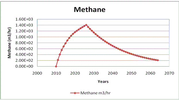
Fig.3 Graph showing methane production.
The power generation capacity of the site will be increased gradually and cost effectively. There will be an increase in the gas production rate over the years, until we get to a capacity of approximately 1200 m3/hr, which translates to 2.7 MW of power production. This comes to an approximate annual power production of 23 million KWh. This capacity could be kept constant for the period of seven years between 2022 and 2028, as shown in the two graphs in Figures 4 and 5 below.
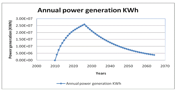
Fig.4 Graph showing estimated annual power generation.
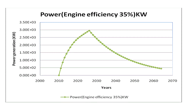
Fig.5 Graph showing power generation.
It is important to note that the gas structures will be installed in phases from phase 1 to phase 8, to be in line with the actual filling of the landform. Completion and capping of phase 1 of the landfill site will be followed by drilling and gas extraction from this phase alongside the filling of phase 2. Electricity generation from the gas extracted from phase 1 will start approximately one year into the filling of phase 2 as it is assumed that this is when phase 1 will reach gas production capacity, enough for power generation. Until then, extracted gases will be flared, as stated earlier in this report.
The completion and capping of the other phases will also be followed by drilling gas extraction wells to add to the existing gas extraction capacity. The increased gas production is also met with an increase in the power-generation capacity, with the excess gases being flared.
Design Considerations:
- Proper gas monitoring is done to ensure no gas leakages, especially from the periphery of the site.
- The gas engine has a conversion efficiency of 35%.
- Flaring in the enclosed flare stack takes place at 1000 oC, ensuring contaminant destruction.
- For the purpose of this report, an analysis over a 55-year period from 2010 to 2064 is given.
- All values used where estimated use the landgem software provided, which gives an assumed methane content of landfill gas as 50%.
- A safety requirement for gas handling is the installation of flame arrestors to reduce explosion risks.
- Siting of the gas-utilisation system takes into account the prevailing wind and sensitive receptors.
- The products of combustion and flaring will be tested to ensure performance standards are attained.
The process-flow diagram in Figure 6 below gives a general description of the overall gas-handling system.
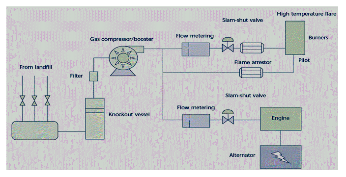
Fig.6 Overall gas handling system arrangement.
3 SITE RESTORATION PLANS
Consideration should be given to the visual appearance of the landform during operation and at termination of landfilling and its impact on the surrounding landforms (EPA, 2000). On this note, it is easy to assume that site restoration just implies giving the landfill site a good visual appearance, but this is not the case. The filling process and, especially, the landfill capping play a vital role in decisions made about site-restoration plans that are considered during the design of the landfill site. ‘The proposed after-use can affect the rate of evapotranspiration from the restored surface, which in turn affects the degree of infiltration of water into the landfill and thus the rate of leachate generation’ (EA, 2007).
It is therefore important to note that the capping design chosen must be able to accommodate the site restoration and after-use of the landfill site. In general, landfill caps have to be designed to minimise the ingress of precipitation into the landfill. This is to check leachate generation while promoting increased waste degradation. It also allows for surface stability to minimise renegade emissions of LFG via the surface of the capping layer. This is achieved by integrating the capping layer with the gas-collection system. The capping layer should also effectively disconnect the waste in the landform from its surrounding environment.
A lot of after-use options exist for landfills on closure, but it is important to select an option which suitably matches the contents of the landfill (which can affect its settlement characteristics), the capping system, the normal use of land in that area and the surrounding landscape, to mention but a few.
For this site, it is proposed that the landform be covered by a geo-synthetic liner, followed by an average cover of approximately 1.5 m of top-soil and sub-soil. A water-collection system will be integrated into the capping layer to collect run-off water. Restoration for after-use of the site, which will follow each completed capping phase, will combine three options to give a more attractive and useful end result. These options are agriculture, amenity and recreational use (to include walk and cycle paths) and the provision of mixed woodlands.
Design Considerations:
- The soil required for restoration purposes is available and accessible and will be mixed with compost.
- The proposed restoration and after-use plans are accepted by local residents and interest groups.
- The restoration is to be done in phases, in line with each completed phase of the landform, allowing the restored phase to form a visual and acoustic barrier and establishing the restoration scheme early. This will allow for maturation while landfilling operations go on.
- Interim measures will be put in place to allow for regular maintenance of the site, e.g. gas well re-drilling.
- Proper aftercare, maintenance and management of the restoration scheme are also included in the proposal.
- It is assumed that proper consultation from the respective professionals was carried out, to have come up with this proposal.
- The proposed restoration plan would be cost effective.
4.0 RECOMMENDATIONS
Recommendations for this stage of the design focus on efficient gas utilisation. It is very difficult, if not impossible, to make full use of the LFG being produced from the site for power generation. One major reason for this is that gas from the landfill is produced at a variable rate. It is also dependent on various unknowable factors within the landform such as rate of degradation, moisture quantity, etc. As the gas engines can only use the produced gases for combustion at a fixed rate, it is practical to install engines with a gas-consumption rate below the average gas-production rate, so that there is always a steady supply of LFG for the gas engines. This gives rise to the need for continuous flaring of a large quantity of gas. ‘In the UK to date, the amount of gas being flared on Landfill sites equates to a gas-generating capacity of: 400 Mw/Hr or £500,000.000 per year. The gas being flared is gas that is not capable of being economically exploited to produce renewable electricity’ (Tetchner, 2008).
It is, however, possible to make the gas utilisation process more efficient by using the heat generated from the combustion in the engines and also during flaring (as this is carried out in enclosed flares at temperatures of over 1000 oC). This can be achieved by installing combined heat- and power-generation schemes; while generating power, the heat generated from combustion and flaring can be used for space heating. Also, it might be possible to partner with an industry such as the cement industry, to develop a system where heat generated can be used for cement kilns.
At the early stage of gas production, before power generation becomes cost effective, it might be more sustainable to contain the extracted gases for exporting to some other, older site. Such a site would have the capacity to utilise these gases due to reduced gas production from its landfill.
5 CONCLUSION
LFG is a very useful resource and should therefore be exploited as profitably as possible. This entails integrating efficient technology into the processes of collection and use of this resource, as shown by this design.
Profitable use of a landfill site after closure depends on implementation of proper restoration practices. Of course, this is also depends on proper landfill practices being carried out and should always be an integral part of the landfill-site design.
REFERENCES
Department of Environment, 1988. Waste Management Paper No. 26. Landfilling Wastes. A Technical Memorandum for the Disposal of Wastes on Landfill Sites. HMSO Publication Centre, London.
Environmental Agency, 2007. Focus: “Guidance on Gas Treatment Technologies for Landfill Gas Engines”. [Internet]. Available at http://www.environment-agency.gov.uk/commondata/acrobat/lftgn06_treatment_936556.pdf. [accessed 21 November 2008].
Environmental Protection Agency, 2000. Focus: “Landfill Manual, Landfill Site Design”. [Internet]. Available at http://www.epa.ie/downloads/advice/licensee/epa%20landfill%20site%20design.pdf. [accessed 20 November 2008].
Forbes McDougall, Peter White, Marina Franke, Peter Hindle,(2003), ‘Integrated Solid Waste Management: a Life Cycle Inventory’, Blackwell Publishing:2003DoE, 1988.
Gerald Tetchner, 2008. Resource material (2006). Landfill gas utilization. University of Leeds, School of Civil Engineering Leeds.
Ministry of The Environment, 1998. Focus: “Landfill Standards. A guideline on the Regulatory and Approval Requirements for New or Expanding Landfilling Sites”. [Internet]. Available at http://www.ene.gov.on.ca/envision/land/landfill/index.htm. [accessed 20 November 2008].