Direct Velocity, Direct and Compensated Acceleration Feedback Control Systems in Mitigation of Low-frequency floor Vibrations
A Comparison of Direct Velocity, Direct and Compensated Acceleration Feedback Control Systems in Mitigation of Low-frequency Floor Vibrations
NOMENCLATURE
| X | Displacement vector (n×1) | K | Stiffness matrix (n×n) (N/m) |
| Velocity vector (n×1) | k | Modal stiffness (N/m) | |
| Acceleration vector (n×1) | ζn | Modal damping ratio | |
| F | Force vector (n×1) | ωn | Natural modal frequency (rad/s) |
| M | Mass matrix (n×n) | g | Feed-back gain |
| M | Modal mass(Kg) | GA (jω) | Actuator’s transfer function |
| C | Damping matrix (n×n) | Gs (jω) | Sensor’s transfer function |
| Cm | Modal damping | G (jω) | Plant’s transfer function |
ABSTRACT
Numerous control systems, passive, active and semi-active, have been developed by past research to mitigate undesirable vibrations in civil engineering structures. Active vibration control (AVC) is emerging as a realistic option for the mitigation of human-induced vibrations in office floors. Some AVC control laws commonly associated with vibration mitigation that have been investigated within this research include direct velocity feedback (DVF), direct acceleration feedback (DAF) and compensated acceleration feedback (CAF). The research presented in this work evaluates the bandwidths of effectiveness of the vibration mitigation performances of each of these AVC control laws for some idealised single-degree-of-freedom (SDOF) models of a floor structure with frequencies ranging from 1 Hz to 20 Hz. Modal masses and damping ratios of these SDOF floor representations have been kept constant. It was found that DVF performs best in low-frequency floors while DAF performs well at much higher frequency floors. CAF performs quite well in both the low and high frequency floors used in these studies.
1. Introduction
Recent advances in construction materials and design technologies have led to lighter and thinner structural elements that are architecturally more appealing. Thinner floor structures, the consequence of such advances, often do not meet the vibration serviceability requirements. This problem has been reported in numerous structures like office floors, shopping malls, airport concourses and restaurants, to name but a few (1).
There has been a vast amount of research conducted to mitigate human-induced vibrations in floors. Passive technologies were the typical first generation approach. They employed mechanical elements and devices to dissipate some of the energy in floors and thereby reduce the vibration levels. These technologies do not need any external energy sources and are quite reliable. However, they have limited effectiveness in some instances and have to be tuned to specific dominant modes of vibration (2).
To improve the efficiency of passive techniques, semi-active control was developed. With these techniques, some features of passive vibration mitigation systems can be adjusted in real-time to increase their vibration mitigation effectiveness for a broad spectrum of disturbances. Examples of properties that can be adjusted include the fluid viscosity of viscous dampers as seen in magneto-rheological (MR) and electro-rheological (ER) dampers. There are still numerous issues with regards to their effectiveness in various scenarios, particularly for the mitigation of human-induced vibrations in civil engineering structures.
Active vibration control (AVC) has been developed to make vibration mitigation more efficient and adaptive in, for example, floors affected by human-induced vibrations. This is not the ultimate solution and has some potential drawbacks in itself. An active control system, in its simplest form, comprises a sensor to monitor the structural response, a control algorithm to compute the required control signal and an actuator to introduce the control force (3).
Within AVC studies, several control laws exist; typical examples make use of feedback loops. Some of the AVC control laws that have been implemented by researchers for mitigation of human-induced vibrations in floors include DVF, DAF and CAF. Each possesses both advantages and disadvantages, which makes a proper selection of the best one to implement in a particular application a complicated process.
This paper investigates the vibration mitigation performance of DVF, DAF and CAF control laws on some idealised SDOF floor slabs with variable dynamic properties; that is, frequencies ranging from 1 Hz to 20 Hz. The modal masses and modal damping ratios have been kept constant in all the models. This will give an indication of what type of control system can be implemented in a floor structure of given modal properties. Actuator dynamics and sensor dynamics have been considered in all the cases, where the sensor dynamics refer to the dynamics of the integration circuit. Root locus studies are used to evaluate optimal control gains that are implemented in the analytical studies. Analytical studies comprise heel-drop tests making use of an idealised triangular pulse and walking excitation measured from treadmill tests. For heel-drop excitation, the time for the response to decay to 5% of its peak is used as the performance indicator. For walking excitation, the peak value of the 1s running RMS (MTVV) has been used as the performance indicator. Some root locus plots are presented to elaborate on the reasons for the vibration mitigation performances attained.
2. Dynamics of Control System Components
2.1. Floor Models
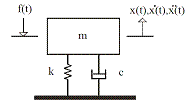
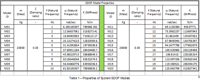
In this research, SDOF models as shown in Figure 1 and with a linear, constant coefficient differential equation taking the form of Eq.1, have been selected to represent the dominant modes of some 20 idealised, simply supported floors of different modal properties. The dominant modes of these floors have been assumed to have natural frequencies ranging from 1Hz to 20Hz, as highlighted in Table 1. The modal masses and damping ratios of each of these models have been assumed to be constant. This aids in evaluating the possible bandwidths of efficiency of each of the AVC control laws (noted in the abstract) for vibration mitigation of floors of different modal properties. For a collocated sensor/actuator pair in each idealised floor representation, the transfer functions of each of these models can be represented as shown in Eq. 2.
![]()
![]()
Where m is the modal mass, c is modal damping and k is the modal stiffness, s = jω, ω is the frequency, χi , ζi and ωi are the inverse of the modal mass, the damping ratio and natural frequency associated with the ith mode, respectively.
2.2. Actuator Dynamics
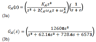
The proof-mass actuator considered in this research is an APS dynamics Model 400 mechanical shaker. It has a 30.4kg reaction mass and its estimated natural frequency is 1.8Hz. The dynamics can be closely modelled by the linear third-order model in Eq. 3. KA>0, and ξA and ωA are, respectively, the damping ratio and natural frequency of the actuator. The pole at –ε provides the low-pass characteristics of this actuator (2).
2.3. Sensor Dynamics
The sensor dynamics, i.e. the dynamics of the integrator circuit used in these studies can be modelled by the filter in Eq. 4.

3. Control Laws
Three different control laws used for mitigation of human-induced floor vibrations in previous research include DVF, DAF and CAF (ref). The vibration mitigation performance bandwidths of these control laws for human- induced vibrations are investigated in this AVC research on some idealised floors whose modal properties have been presented in section 2.1. The human excitation forces that have been used in the analytical studies, briefly described in section 4, are comprised of an idealised heel-drop excitation force (1) as well as real walking excitation forces, obtained from treadmill tests at the University of Sheffield.
A voltage saturation level of VL= 0.5V has been introduced in the analytical studies. In principle, this is the saturation voltage that would be implemented in the experimental implementation of the AVC system. The three control laws noted in the previous paragraph will now be briefly introduced.
3.1. Direct Velocity Feedback (DVF)
With the DVF control law, for a collocated sensor and actuator control system, sensor outputs (velocity) are multiplied by pre-selected control gains and these are fed back to the collocated actuators as expressed in Eq. 5.

3.2. Direct Acceleration Feedback (DAF)
For the DAF control law, also considering a collocated sensor and actuator set-up, sensor outputs (acceleration measurements in this case) are multiplied by pre-selected control gains to generate the control signal that is then fed to the actuator amplifier to drive the actuators. This is presented in Eq. 6, with the control set-up being presented in Figure 3.

3.3. Compensated Acceleration Feedback (CAF)
To increase the stability of the DAF system and make it more amenable to the introduction of significant damping, a phase-lag compensator can be designed. The CAF set-up as designed in previous research (2) is represented in Figure 4.

4. Human Excitation Forces
The excitation forces used in the analytical studies presented in this paper include an impulsive excitation force and a real walking force time history obtained from treadmill walking tests. These excitation forces are presented in the following sub-sections.
4.1. Heel-drop Force
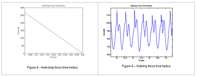
The heel-drop excitation force can be conceptualised as a triangular pulse with a peak force of 2670N, reducing to zero in a time of 0.05s, which corresponds to an impulse of 67Ns (1). This is shown in Figure 5.
4.2 Walking Excitation
Walking force time histories obtained from treadmill walking tests in the University of Sheffield light structures laboratory were used in the analytical studies. The walking force specifications are: body weight: 886N, walking speed = 1.2085m/s equivalent to 1.7Hz pacing rate (and further assuming a 70cm step length). This is shown in Figure 6.
5. Simulation Results
The three techniques chosen to evaluate the efficiency of DVF, DAF and CAF control schemes for vibration mitigation of the idealised floor systems noted earlier include:
- An investigation of the damping introduced by the control systems (DVF, DAF and CAF) into the primary structure by reference to the root locus studies of the closed-loop systems.
- A study of the MTVV, described as the peak of the 1s running RMS of the uncontrolled and controlled (DVF, DAF and CAF) responses for walking excitation only.
- A study of the time it takes for the uncontrolled and controlled responses to decay to 5% of the initial peaks for impulsive excitation only.
5.1. Damping Ratio
The closed-loop systems for each of the setups in Figures 2, 3 and 4 can be described by the transfer function representation in Eq. 7. This incorporates the primary structure, actuator and sensor (integrator circuit) dynamics. G(jω) is the transfer function of the floor, GA(jω) is the transfer function of the actuator, Gs(jω) is the transfer function of the sensor and Gc(jω) is the transfer function of a compensator, if any.

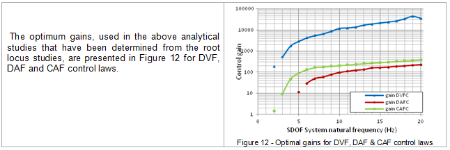
By making use of root locus studies for the transfer function representation in Eq. 7 for each of the idealised structural models, optimum gains were evaluated as presented in section 5.4 as well as maximum damping introduced into each of the structural models.

5.2. MTVV Studies (For Walking Excitation Only)
The optimum gains evaluated in the root locus studies in the previous section and presented in section 5.4 are implemented in these analytical studies for DVF, DAF and CAF control laws. The MTVV is defined as the peak of the 1s running RMS acceleration response of both the uncontrolled and controlled structures. A typical plot of the responses of an open and closed-loop system and the corresponding 1s running RMS acceleration are shown in Figure 8.
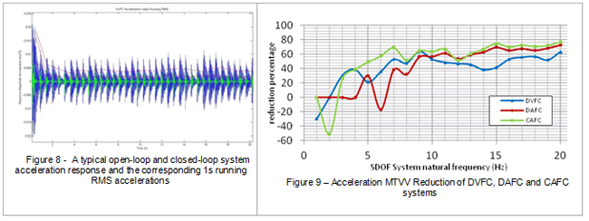
The trends of the reduction in peak values of the 1s running RMS accelerations (MTVV values) of the closed-loop (for DVF, DAF and CAF) responses in comparison with the open-loop system responses are plotted in Figure 9. Again, it can be see that DVF exhibits better vibration mitigation performances at low frequencies and CAF exhibits better vibration mitigation performances at high frequencies.
5.3. Reduction in Decay Time (For Heel-drop Excitation Only)
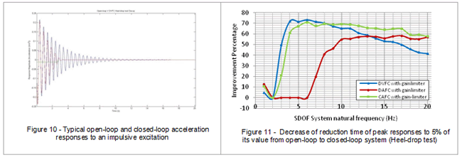
The optimum gains determined from the root locus studies in section 5.1, presented in section 5.4, are used in the analytical studies in this section for each of the idealised structural models. The time for the responses to decay to within 5% of the initial peak is used to evaluate the vibration mitigation performance of DVF, DAF and CAF for each of the structural models subjected to an impulsive excitation force. Figure 10 shows a typical open-loop and closed-loop response. Figure 11 shows the vibration mitigation performances for each of the control laws implemented on each of the idealised structural models as percentage improvements. Again, it can be seen that DVF performs best at low frequencies while CAF performs better at higher frequencies.
5.4. Optimum Gains
6. Results from Analytical Studies
6.1. DVF Control Law
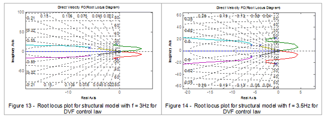
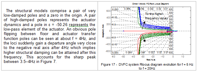
From Figures 7, 9, and 11, it can be seen that DVF is more effective in predominantly low-frequency floors, i.e. between 3Hz and 10Hz. Figure 7 exhibits a sharp peak between 3–4Hz and there is a gradual decrease in higher frequencies. DVF does not have any significant effect on the very low frequency floors, i.e. with natural frequencies ranging between 1Hz and 3Hz as a result of the actuator dynamics lying within this range.
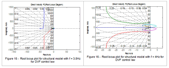
Some root locus plots of some of the idealised floor models in Figures 13, 14, 15, 16 and 17 aid in justifying the observed vibration mitigation performances with DVF control law.
6.2. DAF Control Law
From Figure 7, it can be seen that DAF control law does not offer any significant influence on the dynamic properties of the idealised models with natural frequencies below 5Hz. Above 5Hz, however, the damping introduced into the system gradually increases almost linearly. This can be explained by considering the results from the root locus studies presented in Figures 18, 19, 20 and 21.
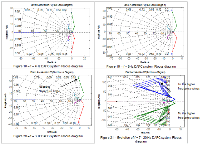
No pole flipping occurs in these closed-loop systems. For idealised structural models with modal properties between 1Hz and 5Hz, the departure angles of the loci of models are located in the right half plane towards the positive real axis. This indicates a near-unstable scenario with a very low damping value. This positive departure angle introduces much less damping than the open-loop damping of the structural models. For idealised structures with natural frequencies above 5Hz, the departure angles of the loci gradually change clockwise from positive to negative values. A gradual evolution of the root locus plot for structural models above 7Hz can be seen in Figure 21.
6.3. CAF Control Law
CAF control law is an integrated version of DVF and DAF control schemes. It aims at utilising the advantages of DVF in lower frequencies and DAF in higher frequencies. This can be seen in Figure 7. The zero of the compensator at ‘–a’ improves the system’s stability by inducing higher damping as well as attracting the system poles after pole flipping. Figures 22, 23, 24, 25, 26 and 27 highlight the evolution of root locus plots of the closed-loop systems for the idealised structural models noted earlier.
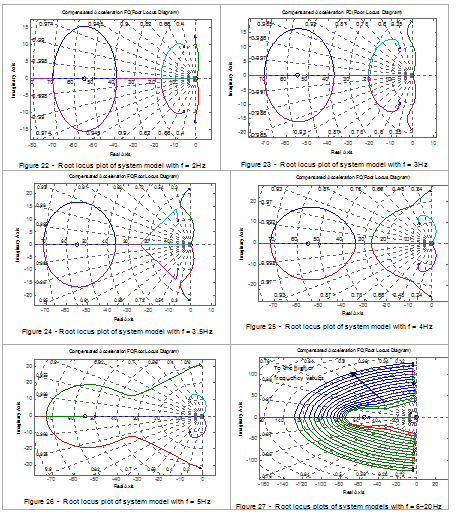
Two pole flipping phenomena can be seen in Figures 25 and 26. The first one happens between f = 3.5Hz and f = 4Hz, where the new floor loci show higher stability and damping. The second one happens between f = 4Hz and f = 5Hz where phase-lag compensator zero at ‘-50.26’ attracts one of the system poles that makes the system highly stable and damped.
7. Conclusion
DVF performs best for low-frequency structural models while DAF has a tendency to perform better at higher frequencies. CAF acts quite well in both in mid-range and high frequency floors; there is still a problem with implementation in low-frequency floors. Finding proper compensators for mitigation of vibrations in very low-frequency structural models is an exciting challenge and an ongoing area of research.
Acknowledgement
The first author is very grateful to Mrs. Legha Shahabpoor for her kind care and support.
Bibliography
Linda M. Hanagan, Thomas M. Murray. Active Control Approach for Reducing Floor Vibrations. s.l. : Journal of structural engineering, November 1997, Vol. 123, pp. 1497-1505.
Ivan M.Diaz, Paul Reynolds. Acceleration Feedback control of human-induced floor vibrations. 2009.
A. Preumont. Vibration Control of Active Structures: An introduction. Dordrecht, The Netherlands : Kulwer Academic, 1997.
Reynolds P, Diaz IM, Nyawako DS. Vibration testing and active control of an office floor. Orlando, Florida, USA. : In: proceedings of the 27th International Modal Analysis Conference, 2009.
Diaz IM, Nyawako DS, Reynolds P. On-Off nonlinear velocity feedback control for cancelling floor vibrations. St.petersburg, Russia : proceeding of the 4th Europen Conference on structural Control, 2008. Vol. 1, pp. 175-82.